
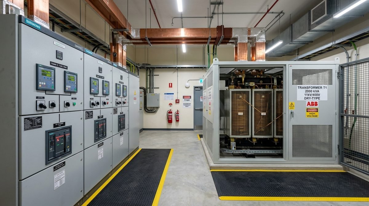
EMF Equation of Transformer
The electromotive force (EMF) equation of a transformer helps calculate the induced voltage in both the primary and secondary windings of the transformer. When we apply an alternating current (AC) source to the primary winding, it generates a current known as the magnetizing current. This magnetizing current produces an alternating magnetic flux in the core of the transformer. This flux forms the basis of how transformers operate and how they transfer electrical energy from one winding to another. In a transformer, the alternating flux produced in the primary winding becomes connected to the secondary winding through a process called mutual induction. Since the flux is alternating, it continuously changes direction and magnitude. According to Faraday’s law of electromagnetic induction, if a conductor or coil links with a changing magnetic flux, an EMF will be induced in it. This phenomenon occurs in both transformers and induction motors, as they share similar fundamental principles.Understanding the EMF Equation of a Transformer
To determine the magnitude of the induced EMF in a transformer, we use the EMF equation. Let’s look at the parameters involved in this equation. Let’s denote:- N1N_1: Number of turns in the primary winding
- N2N_2: Number of turns in the secondary winding
- ΦmPhi_m: Maximum magnetic flux in the core, measured in Weber (where Φm=Bm⋅APhi_m = B_m cdot A)
- ff: Frequency of the AC input, in hertz (Hz)
Calculating the Average Rate of Change of Flux
The average rate of change of flux during this quarter cycle is: Φm1/(4f)=4fΦm Wb/s or voltsfrac{Phi_m}{1 / (4f)} = 4f Phi_m , text{Wb/s or volts} This rate of change of flux per turn represents the induced EMF, measured in volts. So, the average EMF per turn is: 4fΦm volts4f Phi_m , text{volts} However, if the flux ΦmPhi_m varies sinusoidally (as it does in most AC applications), we need to calculate the root mean square (RMS) value of the induced EMF. To do this, we multiply the average EMF by the form factor. The form factor for a sinusoidal waveform is 1.11. Thus, the RMS value of EMF per turn is: 1.11×4fΦm=4.44fΦm volts1.11 times 4f Phi_m = 4.44f Phi_m , text{volts}Calculating the Total EMF in Primary and Secondary Windings
Now, let’s look at the total EMF induced in both the primary and secondary windings of the transformer.Primary Winding
The RMS value of the total EMF induced across the primary winding, denoted as E1E_1, is: E1=4.44×f×N1×ΦmE_1 = 4.44 times f times N_1 times Phi_m Since Φm=Bm⋅APhi_m = B_m cdot A, where BmB_m is the maximum flux density and AA is the cross-sectional area of the core, we can also express this equation as: E1=4.44×f×N1×Bm×AE_1 = 4.44 times f times N_1 times B_m times ASecondary Winding
Similarly, for the secondary winding, the RMS value of the total EMF induced, denoted as E2E_2, is: E2=4.44×f×N2×ΦmE_2 = 4.44 times f times N_2 times Phi_m Again, we can write this as: E2=4.44×f×N2×Bm×AE_2 = 4.44 times f times N_2 times B_m times AUnderstanding the Relationship Between Primary and Secondary EMF
From the equations above, we see that the ratio of EMF to the number of turns is the same for both primary and secondary windings in a transformer. Therefore: E1N1=E2N2=4.44×f×Φmfrac{E_1}{N_1} = frac{E_2}{N_2} = 4.44 times f times Phi_m This equality implies that the EMF per turn is consistent across both the primary and secondary windings. Thus, the magnetic flux in both windings is the same, allowing the transformer to transfer power efficiently from the primary winding to the secondary winding.Voltage Transformation Ratio (K)
Transformers operate based on a concept known as the voltage transformation ratio, often represented by KK. From the EMF equation, we derive the following relationship: E1N1=E2N2=Kfrac{E_1}{N_1} = frac{E_2}{N_2} = K Here, KK is a constant called the voltage transformation ratio. The value of KK depends on the relative number of turns in the primary and secondary windings.- When N2>N1N_2 > N_1, then K>1K > 1. This type of transformer is known as a step-up transformer, as it increases the output voltage relative to the input.
- When N2<N1N_2 < N_1, then K<1K < 1. This type of transformer is known as a step-down transformer, as it decreases the output voltage.
Practical Application of the EMF Equation in Transformers
In practical applications, engineers use the EMF equation to design transformers with specific voltage levels. By carefully choosing the number of turns in each winding, they can create transformers that step up or step down voltages for various applications, such as in power transmission or electronics. For an ideal transformer, which is a theoretical model without any losses, the power input to the primary winding equals the power output from the secondary winding. We know from the power equation of the transformer that: V1=E1V_1 = E_1 and E2=V2E_2 = V_2 where:- V1V_1: Supply voltage of the primary winding
- V2V_2: Terminal voltage of the secondary winding
Conclusion
The EMF equation of a transformer is essential for determining the voltage levels in both the primary and secondary windings. By applying AC voltage to the primary winding, a changing magnetic flux is generated in the core. This flux induces EMF in both windings based on Faraday’s law of electromagnetic induction. The EMF equation provides the foundation for designing transformers that can effectively step up or step down voltages. The voltage transformation ratio, KK, plays a key role in defining whether a transformer will increase or decrease the voltage. Engineers use this principle in power distribution, electronics, and other fields requiring voltage adjustment. Understanding the EMF equation of a transformer helps us appreciate the importance of transformers in electrical and electronic systems around us.Have Specific Equipment or Plant Capacities to Calculate?
Our AI Specialist can troubleshoot technical issues, calculate duct velocity, determine chiller load, or size cables specifically for "".
popeye21834
Licensed Engineering ContributorChartered Senior MEP Engineer & Review Board Specialist with extensive design, testing, and commissioning field experience across commercial and industrial infrastructure.

Leave a Reply