

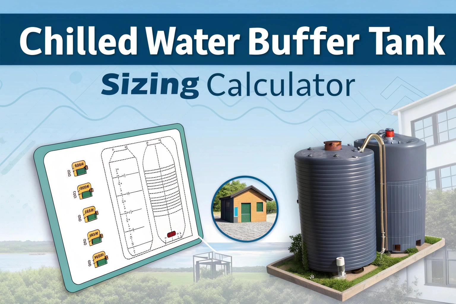
Buffer tank is technique which is used to by engineers to make HVAC system stable, they reduces short cycling of chillers and improves temperature, they obtains stability using multiple techniques one of the most common technique is sizing tank properly, they Use their tank info to make system stable on the sites like buildings, industries etc. they can download excel sheet to calculate tank volume this is very helpful to design process and its completely free all over the world and still its very useful.
Why Use a Chilled Water Buffer Tank?
- Prevents Chiller Short Cycling: Maintains minimum run‑time by providing additional thermal inertia.
- Stabilizes Load Fluctuations: Smooths out rapid changes in cooling demand from VAV systems or intermittent loads.
- Enhances Temperature Control: Improves ΔT across the system for better comfort and energy efficiency.
- Reduces Wear & Tear: Minimizes frequent start‑stop cycles, extending chiller and compressor life.
Key Inputs & Calculation Method
- Cooling Capacity (RT or kW): Enter the total chiller capacity.
- Design ΔT (°F or °C): Specify the temperature difference between supply and return water.
- Minimum Chiller Run‑Time (minutes): Set desired minimum on‑cycle duration.
- Pump Flow Rate (GPM or L/s): Input primary chilled‑water flow rate.
- Safety Factor (optional): Apply 10–20% extra volume to accommodate system losses.
The calculator uses the formula:
V=Q×t×60ρ×cp×ΔTV = frac{Q times t times 60}{rho times c_p times Delta T}- V = tank volume (gallons or liters)
- Q = cooling capacity (tons × 12,000 BTU/hr or kW × 3412 BTU/hr)
- t = minimum run‑time (hours)
- ρ = water density (~8.34 lb/gal or 1000 kg/m³)
- cₚ = specific heat (1 BTU/lb·°F or 4.186 kJ/kg·°C)
- ΔT = design temperature difference
Using the Excel Tool
- Download & Open: Enable editing in Excel.
- Input System Data: On the Inputs tab, fill in capacity, ΔT, run‑time, and flow rate.
- Check Results: The Sizing tab displays required tank volume and recommended standard tank sizes.
- Review Pump Impacts: See how added buffer volume affects pump flow and system ΔP.
- Export Report: Use the Summary sheet to generate formatted tables for project documentation.
Article Topic Tags:
Found this technical guide useful? Share with fellow engineers:
Engineering AI Co-Pilot
Have Specific Equipment or Plant Capacities to Calculate?
Our AI Specialist can troubleshoot technical issues, calculate duct velocity, determine chiller load, or size cables specifically for "Chilled Water Buffer Tank Sizing Calculator – Free Tool & Guide".

popeye21834
Licensed Engineering ContributorChartered Senior MEP Engineer & Review Board Specialist with extensive design, testing, and commissioning field experience across commercial and industrial infrastructure.
Previous Article
Fire Extinguisher Training Manual PDF – Free
Next Article
Free Emerson Products Catalogue | Refrigeration PDFs

Leave a Reply