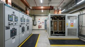
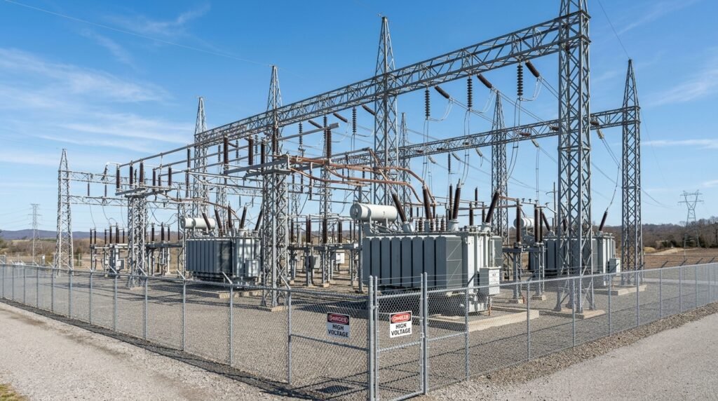
This engineering manual outlines verified diagnostic workflows, mathematical calculations, and safety clearances for Ventilation Calculation for Transformer Room. Adheres to national and international building standards including IEEE / IS 732 / NBC Part 8.
Table of Contents
Designing ventilation for a transformer room could look quite complicated, but once you understand the basics, it feels pretty simple. Transformers produce a lot of heat while they operate, and if this heat doesn’t escape properly, the equipment may be damaged or even fail. That’s why every transformer room needs proper airflow.
I’ll break it down here in a super-easy way, as if to a friend. No major formulas at the beginning, just clear and straightforward steps.
Subscribe to Read Full Engineering Publication
This verified technical document contains complete mathematical derivations, IS/NBC 2016 code references, equipment sizing schedules, and AutoCAD DWG blueprints.
Calculate Exact Formulas for Your Plant Capacity
Need calculations adapted to your exact chiller tonnage, transformer kVA, or fire pump head? Our AI Engineering Specialist is available 24/7 with instant mathematical formulas and code verification.