An Ideal Transformer is a type of electrical device that perfectly transfers the energy between two circuits without any power loss. It efficiently changes voltage levels, making electricity safer and more usable for homes, businesses, and industries.
Imagine a device that transfers energy perfectly, without wasting any power. That’s the beauty of an ideal transformer! It makes high or low voltage safe to use, powering everything from home lights to big industrial machines efficiently.
Stay with us to uncover how an ideal transformer works and why it’s so important in our daily lives. From safely changing voltage to powering homes and industries, this device makes modern electricity possible—let’s explore its magic together!
Types of Ideal Transformers
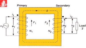
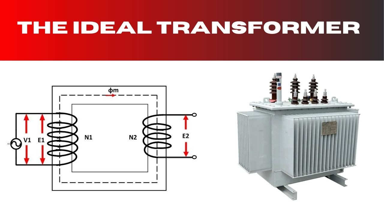
The ideal transformer, which is basically an abstract model, aids in explaining how transformers behave in electric systems. It is defined as a transformer without any losses; by this it means that all energy that is supplied to the primary coil is delivered to the secondary coil intact. It assists engineers in the development of actual constraints that they employ in constructing transformers as it offers the precise way that such devices should perform. In real operational environments there always exists some loss of efficiency but an ideal transformer is a useful concept for studying the actual transformers.
Components
An ideal transformer has two main components: the primary coil and the secondary coil Rarely. These coils are located on a magnetic core which plays an important role in the conversion of electrical energy from the primary side to the secondary side. The two coils have a magnetic connection and the whole exercise follows the operation of a transformer electromagnetic induction. The primary coil, or winding, does receive the AC voltage, which sets up a magnetic environment, or field. The magnetic field produced generates voltage in the secondary coil, and, depending on the number of turns in the secondary coil in relation to the number of turns in the primary coil, this is either stepped up or stepped down.
In an ideal transformer, the essential and optional loops are impeccably attractively coupled. This implies all attractive transition from the essential curl interfaces straightforwardly to the auxiliary loop. Accordingly, the transformer’s productivity is viewed as 100 percent, with no energy lost as intensity, sound, or different structures. Moreover, the ideal transformer expects limitless penetrability in the center material. This permits the attractive field to go through the center with no decrease.
Voltage and Current Transformation
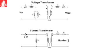
Perhaps, the most crucial aspect of an exemplary transformer is one that defines the perception of voltage and current differences between the primary and secondary sides. The relationship between the voltage and current in the primary and secondary windings of an ideal transformer can be described using two key equations:
- Voltage ratio:
The voltage across the primary coil (V₁) and the secondary coil (V₂) are related by the turns ratio of the coils. The equation is:
V1V2 = N1N2
Where V₁ and V₂ are the voltages in the primary and secondary coils. Respectively, and N₁ and N₂ are the number of turns in the primary and secondary coils.
- Current ratio:
Similarly, the current in the primary coil (I₁) and the current in the secondary coil (I₂) are inversely related to the turns ratio. The equation is as following :
I1I2 = N2N1
In this equation, I₁ and I₂ are the currents in the primary and secondary coils, respectively.
These conditions are pivotal for understanding how transformers lift or buck voltage. At the point when N₂ > N₁, the voltage increments while the ongoing reductions. In the event that the optional curl has a bigger number of turns than the essential loop, the transformer moves forward the voltage and steps down the current. On the other hand if the number of turns in the secondary coil is less than the primary coil (N₂ < N₁), the voltage is induced is less and the current is induced is larger. These adjustment possibilities of voltage and current make transformers so useful in electrical networks.
Power Transfer in an Ideal Transformer
In an ideal transformer, it is assumed that the power delivered from the primary side to secondary side is the same. This is a basic principle which follows the law of conservation of energy, according to which energy cannot be created or destroyed. Therefore, the power on the primary side (P₁) is equal to the power on the secondary side (P₂):
P1=P2
Power is calculated as the product of voltage and current, so we have:
V1×I1=V2×I2
Using the earlier voltage and current relationships, this equation holds true in an ideal transformer. For example, if a voltage is increased on the side of the output transformer secondary winding, then the current will have to decrease on the same side and vice versa, in order to maintain the power value. This is the reason that balance of voltage and current provided to the transformer can make it more efficient and without any wastage of energy.
Impedance Matching
A further advantage of an ideal transformer is the capability as regards the transformation of impedance between circuits. Impedance in an air conditioner circuit addresses protection from flow stream and is key in electrical applications like power circulation and sign handling. Matching impedances guarantees proficient execution in these frameworks. In an ideal transformer, the impedance saw on the essential side is connected to the auxiliary side’s impedance. This not set in stone by the square of the turns proportion:
Z1=N1N22 Z2
Where Z₁ is the impedance seen by the primary coil, and Z₂ is the impedance on the secondary side. By choosing the right turns ratio, an ideal transformer can match impedances between different parts of an electrical system, ensuring maximum power transfer and minimizing signal loss or distortion.
Magnetic Flux and Core Losses
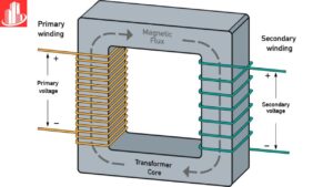
In the real world there is a certain amount of leakage flux. In a transformer core thus core losses in the form of hysteresis and eddy current losses occur. The ideal transformer model accepts that all charging transition goes through each turn of the essential curl. It likewise expects something similar for each turn of the auxiliary loop. This assumption does not require one to include these fundamental losses thus making the ‘ideal transformer’ quite simple.
By and by, transformers are worked with materials of high porousness (µ) to lessen center misfortune, however this misfortune can’t be completely wiped out. The ideal transformer model, in any case, accepts no center misfortune by any means. This supposition gives a valuable establishment to figuring out a transformer’s essential activity.
Applications of Ideal Transformers
The ideal transformer model is fundamental for figuring out applications in power frameworks, gadgets, and media communications. Albeit genuine transformers might have lower productivity, the ideal model remaining parts essential in transformer plan and improvement. Power appropriation transformers depend on voltage and current change standards. These changes empower power to be sent effectively across significant distances. This model consequently shapes the premise of powerful energy transmission strategies. In signal handling, engineers use transformers to match stacking opposition. This guarantees negligible loss of sign strength and power.
Conclusion
An ideal transformer is an essential electrical device that enables efficient energy transfer without power loss, ensuring safe and effective voltage transformation. It focuses on the most beneficial transformer where electricity generated from small home appliances to large industrial machines requires efficient, reliable, and versatile energy supply.
Knowledge of how an ideal transformer works. Enables the individual to value its presence in day to day activities as well as massive industrial processes. By converting high voltages to lower, safer levels and vice versa, it reduces energy waste and maintains stability in power distribution systems. With its zero-loss efficiency in theory, this device represents an ideal standard for electrical engineering. Whether in power grids, homes, or industries, the ideal transformer remains a vital tool in supporting modern energy needs. Making it a cornerstone of electrical advancements.
FAQs
What is an ideal transformer and a real transformer?
An ideal transformer perfectly transfers energy with no power loss. A real transformer, however, has energy losses due to factors like resistance and magnetic leakage.
How do you know if a transformer is ideal?
An ideal transformer has 100% efficiency, meaning there’s no energy loss in the process of transferring power between coils.
What is the ideal transformer law?
The ideal transformer law states that the voltage ratio across primary and secondary coils equals the turns ratio, assuming zero losses.
Where is the ideal transformer used?
Ideal transformers are theoretical but serve as models in electrical engineering to simplify analysis and design of real transformers.
What is an ideal transformer and its properties?
An ideal transformer has properties like no core losses, no resistance in coils, perfect coupling, and 100% efficiency in energy transfer.
