

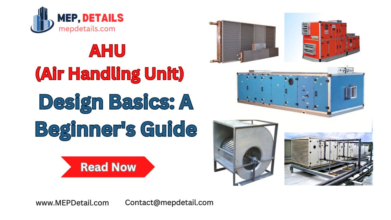
Introduction
The design guidelines and factors for an AHU Air Handling Unit is full foam for commercial or industrial HVAC systems are described in this document. Maintaining a building’s interior temperature, humidity levels, and air quality all depend heavily on the AHU.
AHU (Air Handling Unit) Design Criteria
| Capacity | Calculated based on building size, occupancy, and cooling/heating load requirements. | Cubic Feet per Minute (CFM) |
| Air Quality | Provides adequate filtration to remove particulate matter, allergens, and contaminants from incoming air. | NA |
| Temperature Control | Capable of heating or cooling air as per building’s needs, with precise temperature control. | Degrees Celsius (°C) or Fahrenheit (°F) |
| Humidity Control | Regulates humidity levels within desired range for comfort and health. | Percentage (%) |
| Energy Efficiency | Design considerations include energy-efficient components and systems to minimize operational costs and environmental impact. | NA |
| Noise Levels | Incorporates measures to reduce noise levels for occupant comfort. | Decibels (dB) |
AHU Components Basic Description
| Air Filters | High-efficiency particulate air (HEPA) filters or equivalent for removing fine particles and allergens. |
| Heating/Cooling Coils | Coils connected to a heating or cooling source to adjust air temperature. |
| Humidifier/Dehumidifier | Integrates a humidifier or dehumidifier as needed to control humidity levels based on climate and indoor conditions. |
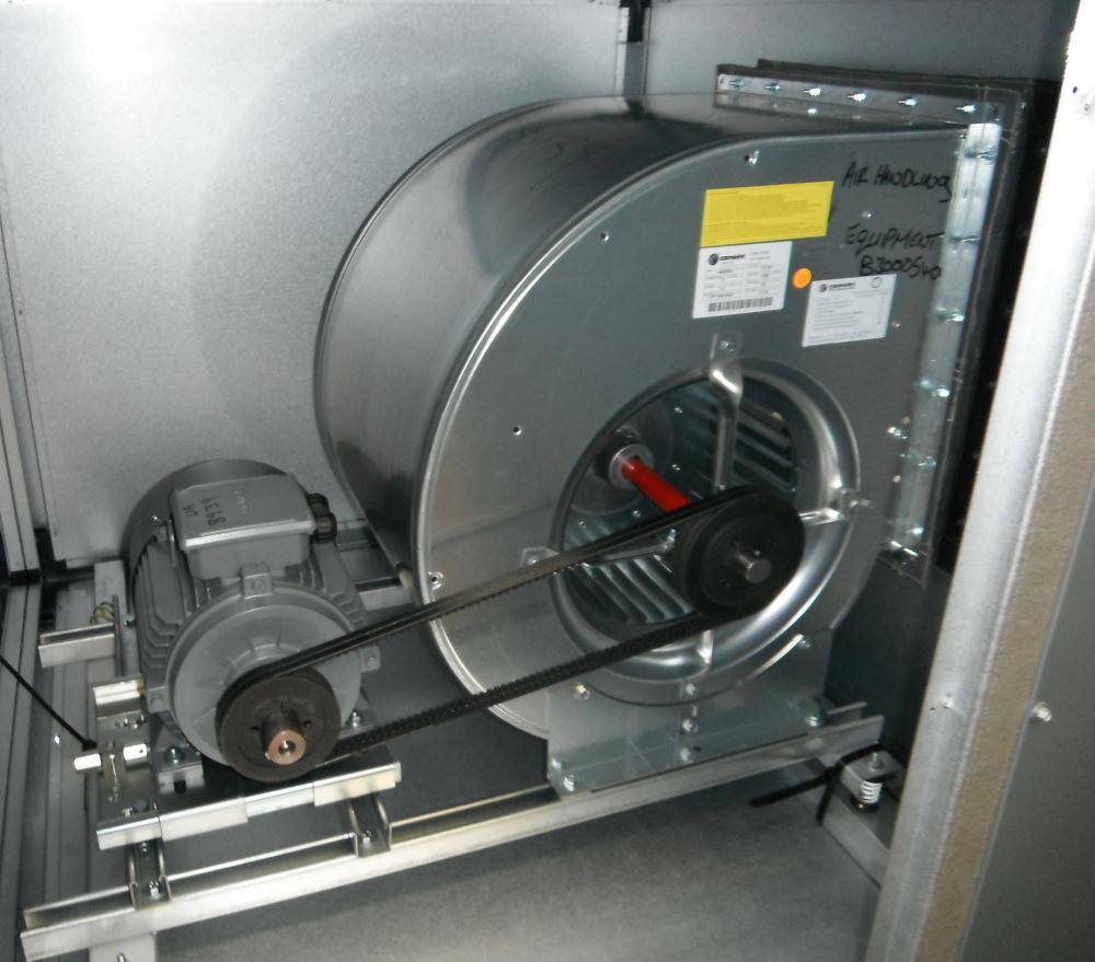
| Fans | Utilizes centrifugal fans to circulate air through the AHU and building ductwork. |
| Dampers | Motorized dampers for controlling air flow within the AHU and adjusting airflow to different zones. |
| Controls | An advanced control system, possibly with sensors, actuators, and a programmable logic controller (PLC). |
| Insulation | Proper insulation of ductwork and AHU components to minimize heat gain or loss and improve energy efficiency. |
| Sound Attenuators | Incorporates sound attenuators or silencers to reduce noise levels generated by the AHU. |
AHU Design Calculation
| Calculation Step | Formula | Result/Value |
|---|---|---|
| Building Area | 10,000 square feet | 10,000 sq ft |
| Occupancy | 50 people | 50 people |
| Sensible Cooling Load (Qs) | Qs = Area × Occupancy × Sensible Heat Factor (SHF) | 375,000 Btu/hr |
| Air Volume (CFM) | Air Volume (CFM) = Sensible Cooling Load (Btu/hr) ÷ (1.08 × Temperature Difference) | 17,361 CFM |
| AHU Capacity Selection | Select an AHU capacity slightly higher than calculated value to ensure adequate cooling capacity | 18,000 CFM |
| Verification | Once installed, commission and test AHU to meet cooling load requirements | Verify AHU performance |
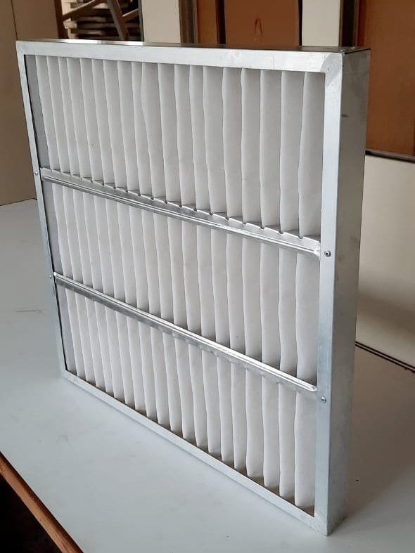
Types of Components with Photos
Direct Drive :
All direct motor drive Air Handling Unit Blowers/Fans are supplied with suitable Electric motor with Fan cooling and also Flame Proof. In Air Handling Unit Blowers/Fans, Impeller are Directly mounted on Shaft of Electric motor. Electric motor in Direct drive Blowers are mounted on M.S. Fabricated Base Plate.
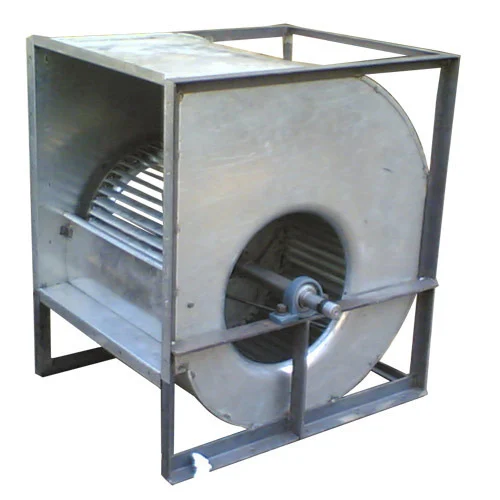
Belt Drive :
All Belt driven Air Handling Unit Blowers/Fans are provided with EN-8 Steel shaft extension running in Ball bearing of different types like Pillow Block Pedestal, Sleeve Type Pedestal, Single bearing Type, etc. Air Handling Unit Blowers/Fans are provided with V type or Flat Pulley of suitable size. Complete Shaft and Bearing systems are mounted on M.
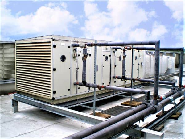
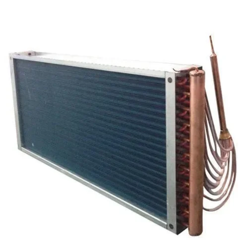
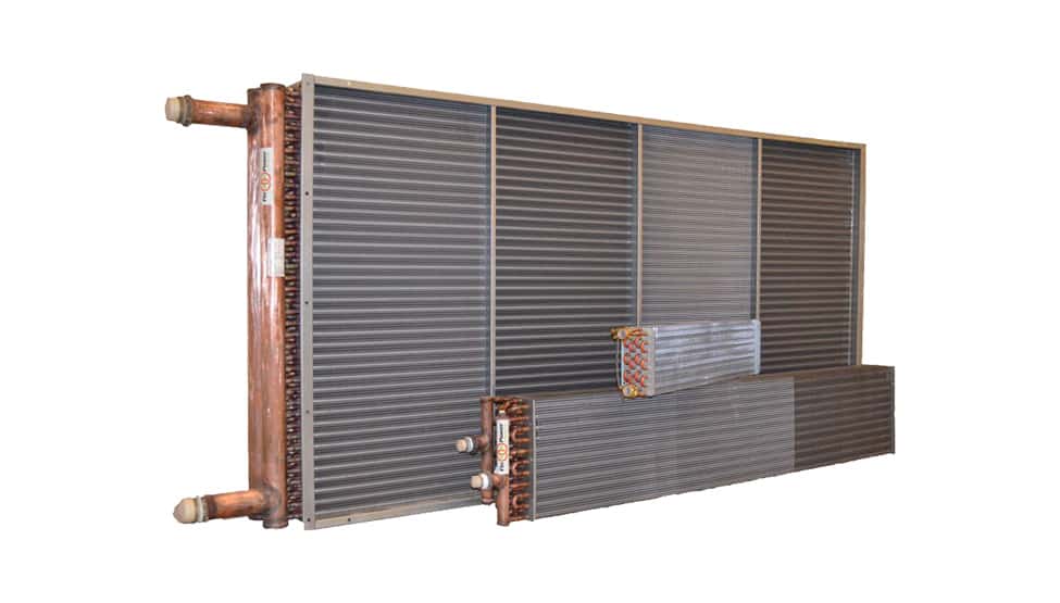
Cooling Coil ( DX & Chilled Water)
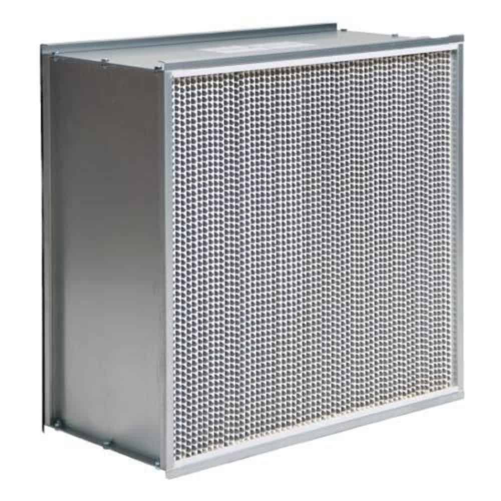
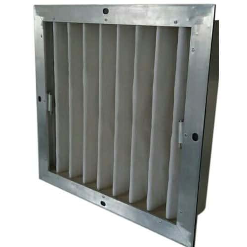
Filters HEPA / FINE / PRE Filter
you may also like – How To Check Ductwork Heat Loss or Heat Gain Analysis -2024