Gaining understanding on how to read pump curves is essential for anyone that is to deal with pimps because it provides an insight of how a pump will perform under various conditions. These bends visually portray the relation between stream rate and head and empowers based to anticipate the working of a pump in a certain network.
In other cases, understanding how to read pump curves may look like a very challenging skill, but it does enhance proficiency while reducing costs and ultimately increasing the longevity of the hardware. These bends provide designs with information needed for intelligent decisions ensuring pumps perform at optimum levels and meet the framework requirements actually.
Please continue with us as we go to a detailed look into how to read pump curves and explain each aspect. By the end of this guide, you will be able to easily interpret pump curves, and apply it in practice with no doubt.
Understanding Pump Curves: Basics and Key Components
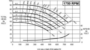
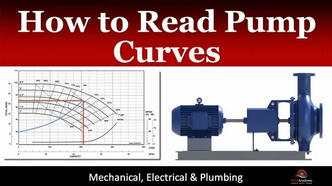
Siphon bends are fundamental instruments for choosing and effectively utilizing siphons. They represent a siphon’s conduct under unambiguous circumstances, supporting designers in settling on informed choices for different applications. The most basic bend is the one that portrays the connection between stream rate (Q) and head (H). This bend gives bits of knowledge into the siphon’s presentation in more favorable conditions. By understanding this relationship, clients can advance siphon activity for more prominent effectiveness. Eventually, siphon bends guide clients in accomplishing the best presentation from their chose siphons.
A siphon bend explicitly shows the stream rate on the x-pivot and the head on the y-hub, representing the siphon’s presentation without outer impacts. This empowers specialists to foresee how the siphon will work under different circumstances, considering variables like speed and impeller width. Most siphon bends likewise incorporate lines addressing power, proficiency, and Net Positive Attractions Head Required (NPSHr). These extra measurements are fundamental while choosing the right siphon for a particular application. By investigating these bends, specialists can go with informed choices to guarantee ideal siphon execution. Understanding these boundaries is urgent for accomplishing effective and solid activity.
A Lesson on Flow Rate and Head Relationship
Both stream rate and head are fundamental reference focuses on a siphon bend, showing the volume of liquid a siphon can deal with and the level it can lift that liquid under unambiguous circumstances. Ordinarily, as the stream rate expands, the head diminishes, mirroring the reverse connection between these two measurements. Understanding this relationship is essential for enhancing siphon execution in stream head applications. Perceiving how a decrease in head corresponds with an expansion in stream rate can fundamentally impact functional effectiveness. This information is imperative for engineers while choosing and overseeing siphons for different frameworks.
For most pumps, the curve slope depicts the variation of performance from one point to another. Stream rate, estimated in gallons each moment or cubic meters each hour, shows the volume of liquid moved over the long haul. Head, communicated in meters or feet, addresses the energy the siphon adds to raise the liquid to a particular level. Together, these measurements assist with evaluating a siphon’s exhibition in moving liquids successfully. Knowledge of these measurements enhances the operation of the pump hence improving costs.
Efficiency Curve: Maximizing Energy Use
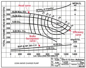
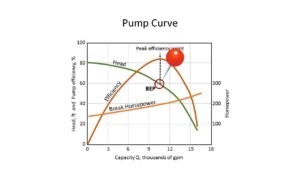
The efficiency curve, which is usually a second curve to pump curves, represents the way a pump bends energy at certain volumetric flow rates. Maximum efficiency is obtained at Best Efficiency Point (BEP) where the cost of pumping is least. When run slightly above the BEP, costs are less, while the components are not worn as quickly and the equipment lasts longer.
Thus, working far from the BEP is possible, but it will result in inefficiency and much wear. If the materials used in efficiency reduce efficiency, more power is called for, increasing energy consumption. It is the engineers’ goal to maintain pump operation within efficiencies as close as possible to the designated typical values by using efficiency curves and selecting the right pump type and size for the specific task within the application.
Electricity Consumption and Brake HorsePower (BHP)
In a few pump curves, the power utilization bend demonstrates the Brake Drive (BHP) required to drive the pump at various stream rates. BHP stands for brake horse power, this is the mechanical energy required for the pump shaft to generate a particular flow rate and head. This curve is applied by engineers to assess power consumption, to check the compatibility with the existing power source.
Brake Horsepower calculations assist the engineers to ensure that the available pumps can adequately support the system requirement without overstraining the motor or causing overheating and pump failure. This measurement is critical in sealing and operation of the pumps to guarantee dependable and secure manners.
Net positive suction head required (NPSHr)
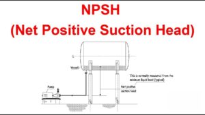
NPSHr is important for process application involving highly flashing or low pressure fluid since it indicates the minimum vacuum required to avoid cavitation. Cavitation leads to formation of bubbles of air which are destructive to the pump. NPSHr is used most of the time on the pump curve as a line rising with the stream rate indicating that higher streams require more vacuum pressure.
The conventional method of ensuring that cavitation does not happen is to make NPSHa to be more than NPSHr. The factors taken into account in the NPSHa include; atmospheric pressure, vapor pressure and the height of suction source. Maintaining suitable NPSHa helps to shield the pump’s impeller and other working parts from cavitation, which raises the gear’s life and effectiveness.
Application of Variable Speed Pump Curves and Control
Present day networks progressively favor variable speed siphons, notwithstanding their marginally higher beginning expenses, because of their adaptability and energy proficiency. Variable speed siphon bends represent what siphon speed and motor head mean for stream rate and power input. By changing the speed, administrators can adjust the siphon’s capacities to the framework’s particular necessities. This capacity decreases energy waste and brings down functional expenses. Subsequently, factor speed siphons add to more productive and manageable siphoning arrangements.
Variable speed drive (VSD) control is a viable framework for siphons, as it gives a consistent and exact reaction to framework stream necessities. In this arrangement, the siphon bend is changed downwards, considering decreased power utilization during low interest. This outcomes in better effectiveness, as the siphon just purposes the energy important for the ongoing stream necessities. The capacities of VSD control work with the effective utilization of assets. Generally, this prompts more economical tasks for associations.
Pump Affinity Laws
Affinity laws are very useful tools for assessing predicted changes in pump performance with speed or impeller diameter changes. These laws allow engineers to evaluate changes and get the pump to the right operational parameters in the shortest time possible.
Affinity Laws:
- The most important relationship between two variables is that the flow rate is proportional to speed of flow.
- Head changes with the square of the speed.
- Power has the cube of speed.
Engineers use these laws to predict performance and energy needs, making affinity laws indispensable for effective pump management.
Key Points for Reading Pump Curves Effectively
To interpret pump curves effectively, keep the following points in mind:
- Identify Flow Rate and Head Requirements: Select a pump that meets application needs while maintaining high efficiency.
- Check the Best Efficiency Point (BEP): Operating close to the BEP optimizes efficiency and reduces wear.
- Review Power Consumption: Ensure the system has enough power without risking overload.
- Compare NPSHa and NPSHr: Verify adequate suction pressure to prevent cavitation, extending pump life.
By following these steps, operators and engineers can select pumps that balance performance, efficiency, and longevity.
Common Errors When Using Pump Curves
Misinterpreting pump curves can result in various issues, from energy inefficiencies to equipment failure. Below are common mistakes to avoid:
- Choosing a Pump Based Solely on Flow Rate: Ignoring head requirements may result in an unsuitable pump.
- Disregarding NPSH Requirements: Failing to check NPSHr can lead to cavitation damage.
- Neglecting Efficiency: Operating far from the BEP leads to higher energy costs and increased wear.
Understanding these errors and focusing on comprehensive pump curve interpretation allows for better equipment selection and operation.
Conclusion
Mastery of how to read pump curves is a commanding knowledge for increasing pump performance and efficiency in various applications. Knowing rate of stream, head, output, and power needs, administrators can make information-driven decisions that incorporate costly errors and offer more stretched out gear utilization. The cooperation of every bend part from the productivity line to the NPSHr is elementary for correct pump execution.
As you continue honing your expertise in how to read pump curves it is very important to remember that accuracy in these curves leads to better, safer and more reliable systems.For sure, these abilities are crucial while changing the siphon speed or choosing the fitting siphon for a particular errand. Understanding stream rate and head guarantees ideal siphon execution for different applications.. Utilizing this information ensures your siphons work within safe parameters, reducing wear and enhancing general system productivity.
FAQs
How do you read a pump curve diagram?
To read a pump curve diagram, locate the flow rate on the x-axis and the head on the y-axis, then follow the curve to see how the pump performs at different points.
What does a good pump curve look like?
A good pump curve should have a clear Best Efficiency Point (BEP) close to the required operating range, indicating efficient and stable performance.
How do you read a turbine pump curve?
In a turbine pump curve, examine the flow versus head, along with efficiency, NPSHr, and horsepower curves, to ensure the pump operates effectively under required conditions.
How to read Grundfos pump curves?
For Grundfos siphon bends, look at the connection between stream (Q) and head (H), as well as productivity and NPSHr. Guarantee your activity stays near the Best Effectiveness Point (BEP) for ideal execution.
How do you read a curve graph?
Identify the x-axis and y-axis variables on the curve graph. Then, follow the curve’s trend to interpret the relationship between these two metrics.
Click On This Link :The Science Behind Corrosion: What You Need To Know


