


Circuit analysis forms a fundamental requirement for the study of electrical engineering, and its role is of significant importance while designing efficient and effective electrical systems. Among a number of tools available to make complex circuits more comprehensible, Millman’s Theorem is one of the essential ones. Through Millman’s Theorem, engineers could make circuit analysis much easier even when the circuits have several parallel branches. This article would explore Millman’s Theorem along with its derivation and practical application in circuit design.
What is Millman’s Theorem?
Millman’s Theorem is named after Professor Jacob Millman, who has amassed a massive amount of knowledge in the field of electrical engineering. This theorem simplifies the calculation of voltage across several voltage sources connected in parallel with resistances. It proves a quite systematic approach toward the replacement of more than one voltage source placed in parallel with one equivalent voltage source along with a resistance.
This theorem is very useful in circuits where the branches are joined in a parallel form that makes it not easy to examine the directly flowing voltage and current. Thus, engineers find an equivalent circuit easier to handle using Millman’s Theorem.
The Statement of Millman’s Theorem
The formal statement of Millman’s Theorem is as follows: If there are n voltage sources with voltages \( e_1, e_2, e_3, \ldots, e_n \) and internal resistances \( r_1, r_2, r_3, \ldots, r_n \) connected in parallel, then these voltage sources can be replaced by a single voltage source \( E \) in series with a resistance \( R \).
- Voltage Sources: \( e_1, e_2, \ldots, e_n \)
- Internal Resistances: \( r_1, r_2, \ldots, r_n \)
- Equivalent Voltage: \( E \)
- Equivalent Resistance: \( R \)
This simplification makes the circuit easier to understand and calculate the voltage and current distribution around the circuit.
Deriving Millman’s Theorem
To develop Millman’s Theorem, the parallel voltage sources must be converted into an equivalent circuit. This involves developing the Norton’s equivalent circuit for the voltage source network and their internal resistances.
Step-by-Step Derivation
To derive the expressions for the equivalent voltage \( E \) and equivalent resistance \( R \), we follow these steps:
- Transform each voltage source and its internal resistance into a current source and parallel resistance using source transformation. For each voltage source \( e_i \) with internal resistance \( r_i \), we have:
- Current Source: \( \frac{e_i}{r_i} \)
- Resistance: \( r_i \)
- Using these transformations, we can represent the entire network as a collection of current sources in parallel with their respective resistances.
- Next, we calculate the total current \( I_n \) at the output terminals. This is done by summing the currents of all transformed current sources:
\( I_n = \frac{e_1}{r_1} + \frac{e_2}{r_2} + \ldots + \frac{e_n}{r_n} \)
- To find the equivalent resistance \( R_n \), we open circuit the output terminals and turn off all current sources. The equivalent resistance between the terminals is the parallel combination of all internal resistances:
\( \frac{1}{R_n} = \frac{1}{r_1} + \frac{1}{r_2} + \ldots + \frac{1}{r_n} \end{p>
- Finally, we can express the equivalent voltage \( E \) as:
\( E = I_n \cdot R_n \)
Practical Application of Millman’s Theorem
Millman’s Theorem can be applied to any real circuit. This theorem would be valuable in engineering since it would make it easier to design complex circuits and permit easier analysis of the behavior and performance of the circuit. With that said, there are a number of actual practical applications.
Power distribution networks: In power distribution systems where multiple generators supply power to a load, Millman’s theorem helps in computing the total voltage and total current supplied to the network.
Electrical Circuit Design : In the design of circuits that use multiple parallel sources of voltage, the theorem makes the computation of total voltage and current flowing through the circuit very simple.
Fault Analysis: Using Millman’s Theorem gives a rapid analysis for how the fault in the circuit impacts the global system performance when a fault is experienced in the circuit.
Limitations of Millman’s Theorem
- You cannot use this theorem in circuits that have both dependent and independent sources together.
- It is not helpful for circuits with fewer than two independent sources.
- This theorem cannot be used for circuits made only of series components.
- It does not work if there is a component between the source and the load.
Dual of Millman’s Theorem
The dual concept to this theorem is referred to as the dual of Millman’s Theorem. This is utilized when the circuit consists of current sources in parallel with their respective resistors. It states that:
If there are n current sources \( I_1, I_2, \ldots, I_n \) and resistances \( r_1, r_2, \ldots, r_n \) connected in parallel, they can be replaced by a single current source \( I \) in parallel with a resistance \( R \).
Deriving the Dual Theorem
The derivation for the dual theorem follows a similar approach:
- Transform each current source into its corresponding voltage source using source transformation:
\( V = I \cdot R \)
- Calculate the total voltage and equivalent resistance using the same principles as in the original theorem, leading to:
\( I = \frac{I_1 \cdot r_1 + I_2 \cdot r_2 + \ldots + I_n \cdot r_n}{r_1 + r_2 + \ldots + r_n} \end{p>
- For the equivalent resistance, simply sum the resistances:
\( R = r_1 + r_2 + \ldots + r_n \end{p>
Conclusion
Electric circuit analysis is made much easier with this Theorem owing to the fact that it focuses on circuits that have several parallel voltage sources. Knowing the theorem along with the principles derived from it enables the engineers to determine the structural and functional features of an electrical system safely and reasonably. Millman’s Dual Theorem, also known as The Millman’s other dual, has extended the versatility of straining the circuit even more as it applies to circuits that have current sources as well.
FAQs
What is Millman’s Theorem?
Millman’s Theorem defines that any number of resistive voltage sources can be lumped together into a single series of VEQ and REQ in order to make a general voltage source.
What is the conclusion of Millman’s Theorem?
It shows that if there are several voltage sources connected with resistances in parallel, they can be replaced by a single voltage source and a resistor in series.
What does Millman’s Theorem say?
It explains that you can replace multiple voltage sources with resistances in parallel by using just one voltage source with an equivalent resistance in series.
How do you verify Millman’s Theorem?
You can verify it by comparing the original circuit and the simplified circuit to check if they give the same result.
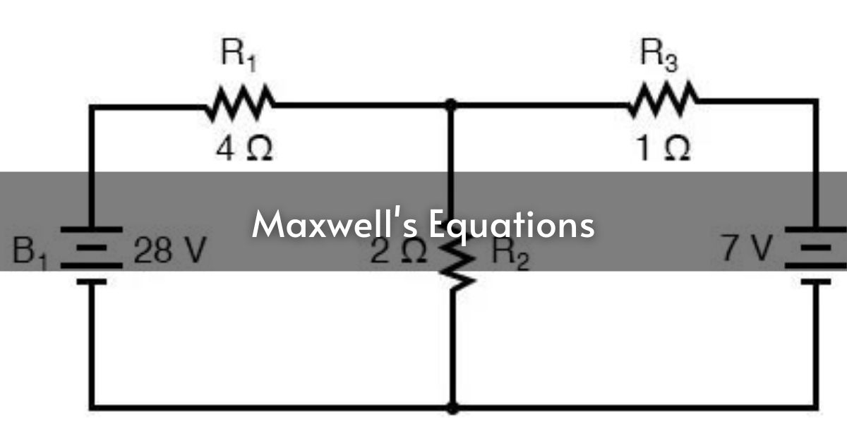
Read More – Maxwell’s Equations: The Foundation of Electromagnetic Theory