


Correctly sizing air terminals and choosing the appropriate air diffusers is vital to ensure HVAC systems that are comfortable, efficient and quiet.
I guide you through a real-world, step-by-step process to translate a calculated airflow (CFM) into an actual Air Terminal Sizing Calculation diffuser size, demonstrate how to differentiate between types of diffusers and show you checks that need running before locking down the selection.
Verifying design airflow per terminal (CFM)
The initial step is determining the supply or return air that has been assigned to the diffuser. This is derived from the room sensible load, ventilation load, and/or the system zoning layout. Use the final design CFM for that particular room or diffuser run, and not an estimated value.
Choose the diffuser or grille type
Selection depends on purpose, aesthetics, acoustic requirements, and mixing method:
| Diffuser/Grille Type | Primary Use Case | Key Features & Benefits |
| Ceiling Swirl or Cone | Supply air in larger rooms | Provides high induction, strong throw and rapid mixing of air. |
| Linear Slot | Perimeter systems & narrow plenums | Sleek aesthetics ideal for curtain effects along windows or walls. |
| Round or Square | General supply air | Simple to install the standard choice for most commercial layouts. |
| Return Air Grilles | Extracting air from a space | High free area design to keep noise low and prevent pressure buildup. |
Decide early because diffuser geometry affects face area, free area, neck size and performance charts you will use.
Pick a target face velocity
Face velocity is the airflow rate over the diffuser face or grille. Low face velocities lead to less noise and draft but need larger area. Typical practical ranges:
- Supply diffusers: ~600 to 1200 fpm (use lower end for quiet spaces, higher for high-throw diffusers).
- Linear slot diffusers: ~600 to 900 fpm (depends on slot geometry and mixing requirements).
- Return grilles: ~350 to 600 fpm (keep low to avoid noise and excessive pressure drop).
Pick a number in that range based on comfort, acoustics and available footprint. Unless the room needs to run a bit quieter I usually set supply at 800 fpm.
The Calculation Steps
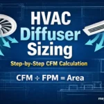
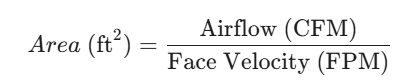
Step A: Calculate Area in Square Feet
The relationship between volume, velocity, and area is linear. Use the following formula:
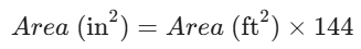
Step B: Convert to Square Inches
Since most HVAC registers and grilles are sold by inch measurements (e.g., 10″ x 6″), you need to convert your result from square feet to square inches. Because 1ft X 1ft X = 12” X 12” the multiplier is 144.
Example
If you are designing a system for a room that requires 400 CFM and you want to maintain a comfortable face velocity of 800 FPM:
1. Find Square Footage:
400 ÷ 800 = 0.5 ft²
2. Convert to Square Inches:
0.5 X 144 = 72 in²
Result: You need a grille with a gross face area of 72 square inches. This could be a 12″ x 6″ grille, a 9″ x 8″ grille, or any combination that equals 72.
Account for free area (open area) and grille factor
The gross face area is not the same as the free (open) area for which the air actually flows. Each diffuser or grille has a free area ratio (FA) or free area percentage that is published at no cost by the manufacturers. Typical free area ratios:
- Standard grilles: 40% to 60% free area
- Perforated diffusers or lined linear slots: 50% to 80% depending on pattern
Adjust the gross area to account for free area:
Required gross area = Required free area / Free area ratio
Continuing the example with a free area ratio of 50% (0.5):
Required gross area = 72 in² / 0.5 = 144 in²
Check neck size and duct connection
This neck must connect to the duct work without creating too high of a velocity or pressure drop. Append neck size to diameter (for circular connectors) or rectangular dimensions. Keep duct velocity through the neck at a reasonable value (generally 800 to 1500 fpm for branch ducts; lower for quiet systems).
Verify throw, spread, and mixing performance
Proper mixing prevents drafts and maintains comfort. Use manufacturer performance charts to verify:
- Throw — distance from diffuser centerline to where the jet slows to a target velocity (commonly 50 or 100 fpm).
- Spread pattern — how the airflow spreads in the occupied zone horizontally/vertically.
- Temperature differential effect — induced velocity depends on supply-air-to-room-air temperature difference.
For perimeter linear slots, check recommended diffuser placement and duct plenum conditions to ensure uniform distribution.
Check pressure drop and noise
Two final performance checks:
- Pressure drop — ensures fan capacity and duct static can deliver required CFM without excessive losses. Pick diffusers with acceptable pressure drop at your selected CFM.
- Sound level — consult manufacturer sound data (NC or dB(A)) at the operating CFM and duct velocities. Reduce face velocity or choose a different pattern if noise exceeds the room criteria.
Finalize selection, coordinate, and balance
After choosing sizes and models:
- Round up to the nearest standard diffuser or grille size the manufacturer provides.
- Coordinate physical sizes with ceilings, lights, and structural elements.
- Specify adjustable necks or balancing dampers where precise airflow balancing will be required.
- During commissioning, measure and adjust each terminal to the design CFM and verify throw, temperature, and noise performance in the actual space.
Quick reference formulas
| Area (ft²) = CFM / Face Velocity (fpm) |
| Area (in²) = Area (ft²) × 144 |
| Required gross area = Required free area / Free area ratio |
| Slot width (in) = Required gross area (in²) / Slot length (in) |
| Round diameter (in) = 12 × sqrt(4 × Area(ft²) / π) |