
Protection For Current‑Graded System: Protection scheme is used to by engineers to prevent damage from the fault currents. they sets relay pickup currents using multiple variations one of the most common technique is grading along a feeder , as we move closer to the power source fault currents becomes more high. they gives each relay a higher pickup setting than its neighbour relay to reduce the time delays. this is completely necessary all over the world and still its very difficult. they use current grading with time grading to make it more reliable and fast. this method is called current-time grading its very useful to prevent fault clearance.
Fundamentals of Current Grading
Fault current magnitude is thing which is depend on distance from source in radial distribution systems. if fault is near substation then current is many times higher than fault at end of feeder. so we can give higher pickup currents when we go near to source.
Firstly we do fault level study we calculate symmetrical short circuit current at main nodes then we select relay pickup current which is more than max load current but less than min fault current at every location for example;
- Feeder end relay: Pickup at 500 A (faults above 600 A).
- Mid‑feeder relay: Pickup at 800 A (faults above 900 A).
- Substation relay: Pickup at 1200 A (faults above 1300 A).
This graded current setting ensures that a fault at the feeder end trips only the furthest relay. Meanwhile, a fault closer to the source trips only the nearer relay.
Key Benefits:
- Faster discrimination than time grading alone.
- Reduced tripping time for downstream faults.
- Straightforward coordination principle.
Grading of current is not enough to give full coordination, there is some uncertain in fault current estimates which can cause miscoordination, also performance of relay in transient conditions can be low, so we usually use current grading with time grading.
Limitations of Pure Current Grading
Although current grading speeds up downstream fault clearance, it has two main drawbacks:
Fault Current Uncertainty is thing which is used to by engineers to check the fault levels in the network. they varies with network changes and load conditions that is why its very difficult to set the relay. if relay is set too close to the lowest expected fault current then it may not trip that is a big problem. and if relay is set too low then it may trip for normal load surges which is also not good.
Relay Performance under Transients is also very important. High‑speed faults and switching surges distort current waveforms that’s why its very difficult to check. Modern digital relays use filters that delay tripping under transient spikes but sometimes it can also lead to misoperation. Under‑damped oscillations can also lead to misoperation which is very bad.
Designer, they cant always use strict current threshold thingy. so they put small time delay so that other device which is downstream can clear fault first. this way is like balanced thing and its basis of current time grading thing.
The Current‑Time Grading Approach
Protection For Current‑Graded System: Current-time grading is technique which is used to by graders to control relays. they obtains current levels and time delay using multiple techniques one of the most common technique is applying delays , Pickup levels and Thresholds. they Use their relay info to make operations on the sites like upstream and downstream etc. this is completely based on current threshold and still its very important.
Principles of Current‑Time Grading:
- Pickup Current Levels is technique which is used to by engineers to set currents. they obtains current levels using multiple techniques one of the most common technique is grading , overlapping and settings. they Use their current info to make settings on the sites like substations, feeders etc. this is very important all over the world and still its very confusing.Time Delay Settings is also very important they use downstream relay with shorter time like 0.2 s. mid feeder relay use moderate delay like 0.4 s and substation relay use longer delay like 0.6 s.Coordination Margin is like margin they leave between relays operating times. they leave at least 0.2 s margin so that downstream relay clear fault first this is completely necessary.
Advantages:
- Speed and Selectivity: Downstream faults clear quickly.
- Backup Protection: Upstream relays provide backup if the primary relay fails.
- Flexibility: Designers can trade off between speed and coordination.
Designing and Implementing a Current‑Time Scheme
Protection For Current‑Graded System: A well‑coordinated current‑time grading system requires a structured workflow:
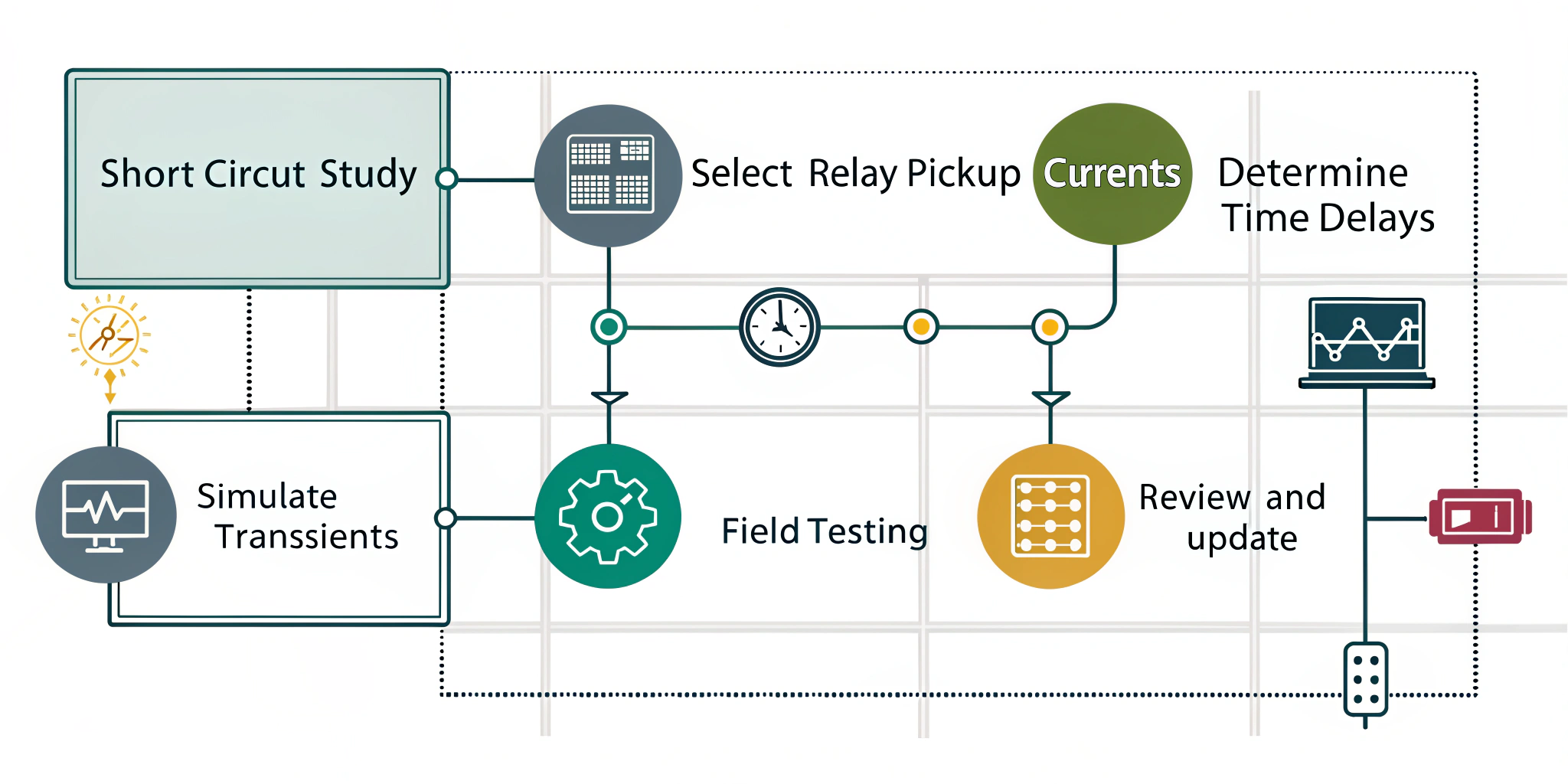
Short Circuit Study is technique which is used to by engineers to find faults in the network. they use software to model faults at different points. they records minimum and maximum fault currents at each relay location. they Select Relay Pickup Currents and set each relay pickup just above the maximum load current. they make sure pickup remains below the minimum fault current at that point.
they Determine Time Delays and start with fastest clearing time for furthest relay. they add coordination margin like 0.2 s for each upstream device. they Simulate Transients and apply current waveforms that mimic switching surges and fault inception. they verify that relays still coordinate under distorted signals.
They do Field Testing and inject test currents and faults to confirm settings. they adjust time delays to fine tune coordination. they Review and Update and re evaluate settings after system upgrades or load changes. they maintain accurate records of coordination curves. this is very important to prevent faults in network.
Case Example:
Relay setting is used to utility to trip the fault. they sets end-of-line relay to 500 A pickup and 0.2 s delay this is one of the most common technique. upstream relay picks up at 800 A with 0.4 s delay they use their relay info to clear the fault. fault at the line end draws 600 A this is completely trip the end-of-line relay in 0.2 s. upstream relay waits 0.4 s before seizing backup operation this is very popular in utility company.
Best Practices and Considerations
- Use Time‑Current Curves: Plot each relay’s curve on a single graph to visualize coordination.
- Maintain Coordination Margins: Keep minimum 0.2 s separation between adjacent curves at all current levels.
- Document Settings: Store relay curves, pickup currents, and coordination studies for future reference.
- Leverage Modern Relays: Intelligent electronic relays can auto‑coordinate settings based on network data.
- Account for Cable Lengths: Longer cables raise impedance and alter fault currents. Adjust settings accordingly.
Grading system alone cant solve all problem of coordination. we use current grading and time grading together it give us speed and selectivity. this method is called current-time grading it help in fast fault clearance and backup protection is also reliable and system stability is improved. if we follow some design process and maintain some margin for coordination then engineer can set relay setting in proper way for any network of distribution.
Protection For Current‑Graded System: FAQs
1. What is current grading?
It sets relay pickup currents higher toward the source to speed up downstream fault clearance.
2. Why combine current and time grading?
Current grading improves speed and time grading ensures proper backup coordination.
3. How do we choose pickup currents?
Perform a short‑circuit study and set pickups between maximum load and minimum fault currents.
4. What margin should separate relay operating times?
Aim for at least 0.2 s between downstream and upstream relay operating times.
5. How often should settings be reviewed?
After network changes, load growth, or relay firmware updates to maintain coordination.
6. Can modern relays automate coordination?
Yes. Many intelligent electronic relays can auto‑coordinate using network models and predefined criteria.
READ ALSO; Voltage to Current Converter
