
Relay Current Settings : Protective relays is like brain of electrical network they detect problem and isolate it so that rest of network keep running. in radial feeder problem can occur any where in line if relay trip to early or to late it can cut of healthy section or it cant clear problem at all so setting correct pickup current and coordinating relay action one by one is very important so that only nearest relay clear problem this way we can minimise interruption of service and reduce stress on equipment.
Coordinating relays is used to prevent cascading failures from happening. they prevents fault deep in the feeder by tripping first relay closest to that fault. if that relay fails then upstream devices must trip without delay. if multiple relays trip at same time then large sections of feeder will lose power. good coordination keeps outages as small as possible. it also speeds up restoration efforts because faulted section is easy to isolate and fix.
Why Relay Coordination Matters
Relay coordination is technique which is used to preserve system stability. when relay clears fault quickly and locally generators and other feeders continue to operate normally. this immediate response limits voltage dips and avoids major disturbances that could cascade thru the network. hence coordinating relays is not just about safety its also about maintenance power quality they use this technique to make system stable like on big sites like power plants etc.
second, coordination is technique which is used to reduce damage to equipment. high fault current is very bad for transformers, cables, and switchgear if it continue for long time. good relay setting stops fault current in mili seconds. by doing this fast, it prevents overheating and mechanical stress on equipment. this way it increase life of equipment and lowers cost of maintenance.
clear co ordination make maintenance easy to do. when engineers do routine testing or repair they can trust relay setting it only protect one section not other areas so they don’t worry about power loss to other neighbouring areas. so teams can do work safely without making big outages.
Calculating Fault Currents and Their Range
Fault current is thing which is different on radial feeder it depend on system generation level and feeder impedance and type of fault. when three phase fault occur under full generation it produce maximum current. and line to line fault with minimum generation it give lowest current. to set relay we need to know about both thing.
Begin by modeling the network under peak generation. This scenario might occur on a cool evening when demand is low but generators run at high output. In this case, the fault current at the end of a long feeder could reach, for example, 12 kA. Next, simulate the weakest generation scenario—perhaps during maintenance or forced outages. A line‑to‑line fault might then produce only 800 A. These two values form the operating range of each relay: it must trip reliably above 800 A and remain stable below 12 kA.
In practice, engineers use network analysis software to calculate fault currents. They enter generator ratings, line impedances, and transformer data. The software outputs current versus fault location. Engineers record the highest and lowest values in each zone. Armed with this data, they can choose pickup settings that lie well within these bounds.
Setting Pickup Currents for Zones
Relay Current Settings : Once fault current limits are known, relay settings follow a logical pattern. The pickup current for each relay must exceed the maximum load current plus a safety margin. It also must be lower than the minimum fault current in its zone. Thus, the relay trips only for true faults and not during normal fluctuations.
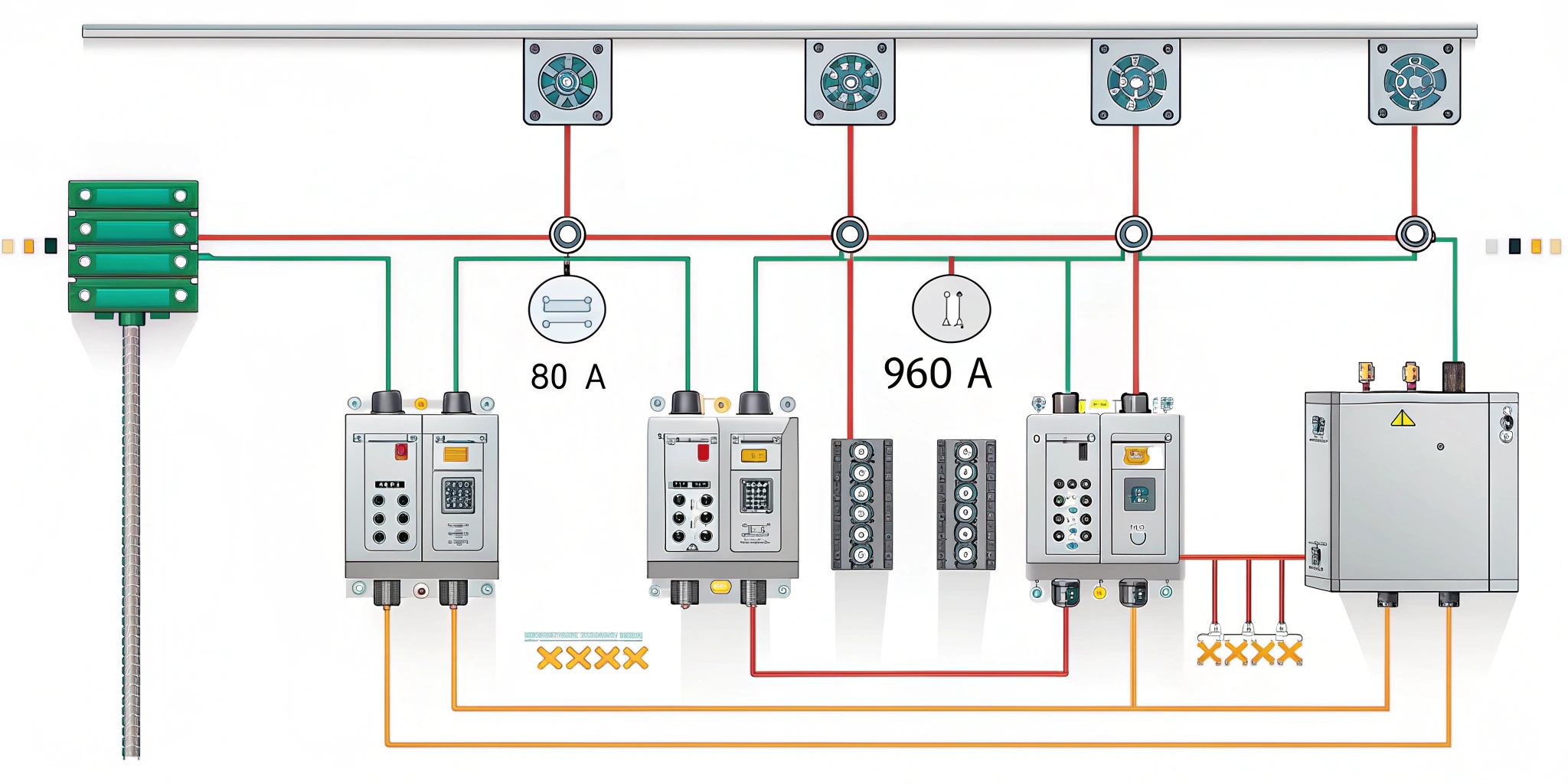
Start at the far end of the feeder. The end‑of‑feeder relay sees the smallest fault currents. Suppose the lowest fault current there is 800 A. Engineers add a margin—often 20 percent—to account for measurement error. This margin brings the pickup to 960 A. At the same time, they confirm that the largest load current plus a safety buffer (say 700 A + 30 percent = 910 A) remains below the 960 A threshold. This ensures the relay does not operate under heavy load.
Fault current is more high here because source is near, it can go up to 1200A, so we put margin and set pickup at 1440A, then we do same thing for each section, we go one section up, and each relay we use pickup more high than downstream device, so zone overlap never happen, we continue this process section by section, upstream relay use more high pickup than downstream one.
Sequencing and Time Grading
Relay Current Settings : Current settings alone cannot guarantee selectivity. Engineers also use time grading—assigning deliberate delays to upstream relays. This staggered timing gives the primary relay a chance to clear the fault first. If it fails, the backup relay trips after its set delay.
For example, end of feeder relay is technique which is used to operate at 960 A with no delay thing. next relay which is upstream it is set at 1440 A it have delay of 0.3 sec. following upstream relay set at 1920 A it delay for 0.6 sec. this time interval thing make sure only one relay trip at one time. if primary relay do its job then backup relay don’t interrupt circuit thing.
Time grading also supports maintenance and fault analysis. When a relay operates with its set delay, it leaves a timestamped record. Engineers use these logs to pinpoint the fault location and the relays involved. Thus, sequencing enhances not only protection but also diagnostic clarity.
Applying Standards and Safety Margins
Relay Current Settings : Relay setting is technique which is guided by national and international standards. they follows standards like Indian standard IS 3427 which says operating current should be at least 30 percent more then pickup setting. this rule is used to compensate for variations in current transformer accuracy, relay calibration and system changes. for example, end-of-feeder relay with 960 A pickup will trip at 1248 A or more.
Beyond current margins, engineers verify settings under real conditions. They inject test currents through the relay circuit to confirm pickup and tripping times. If the relay fails to operate correctly, settings must change. Regular testing—at least annually or after major network modifications—ensures ongoing reliability.
Engineers they checks co ordination when network topology is changing like when new generator is added or feeder is extended or section is reconfigured it can change fault current so after any change they recalculate fault limit and adjust relay setting and all this way protection scheme is alingned with system evaluasion and all.
Relay Current Settings : F&Q
Q1: How do you choose the safety margin for pickup settings?
Engineer peoples they use like 20 to 30 percent as safety margin thing. this range is for transformer tolerance and relay calibration errors and all. you select value which is high enuf to avoid trips but low enuf to catch genuine faults and stuff.
Q2: Can relays share the same pickup current if they are at different locations?
Relay on radial feeder is thing which need to have different setting. upstream relay need to have higher pickup otherwise it will trip before downstream device. if setting is same then it will cause problem of selectivity and outage will be bigger.
Q3: What happens if the primary relay fails during a fault?
if primary relay is not working then upstream relay work after some time this is like backup plan so that fault is clear even primary device is not working this way system is safe
Q4: Why is time grading necessary if current grading is correct?
Current grading alone can fail if fault currents lie between two pickup values. Time grading adds an extra layer of selectivity, allowing primary relays the first opportunity to clear faults before backups intervene.
Q5: How often should you test and verify relay settings?
Testing is thing which we do every year it is like minimum thing we have to do. we also do retesting when we make changes to network like adding new things or changing routes of feeder or changing load and all. doing checks regularly help protection to work good all time.
READ ALSO ; Protection For Current‑Graded System
