

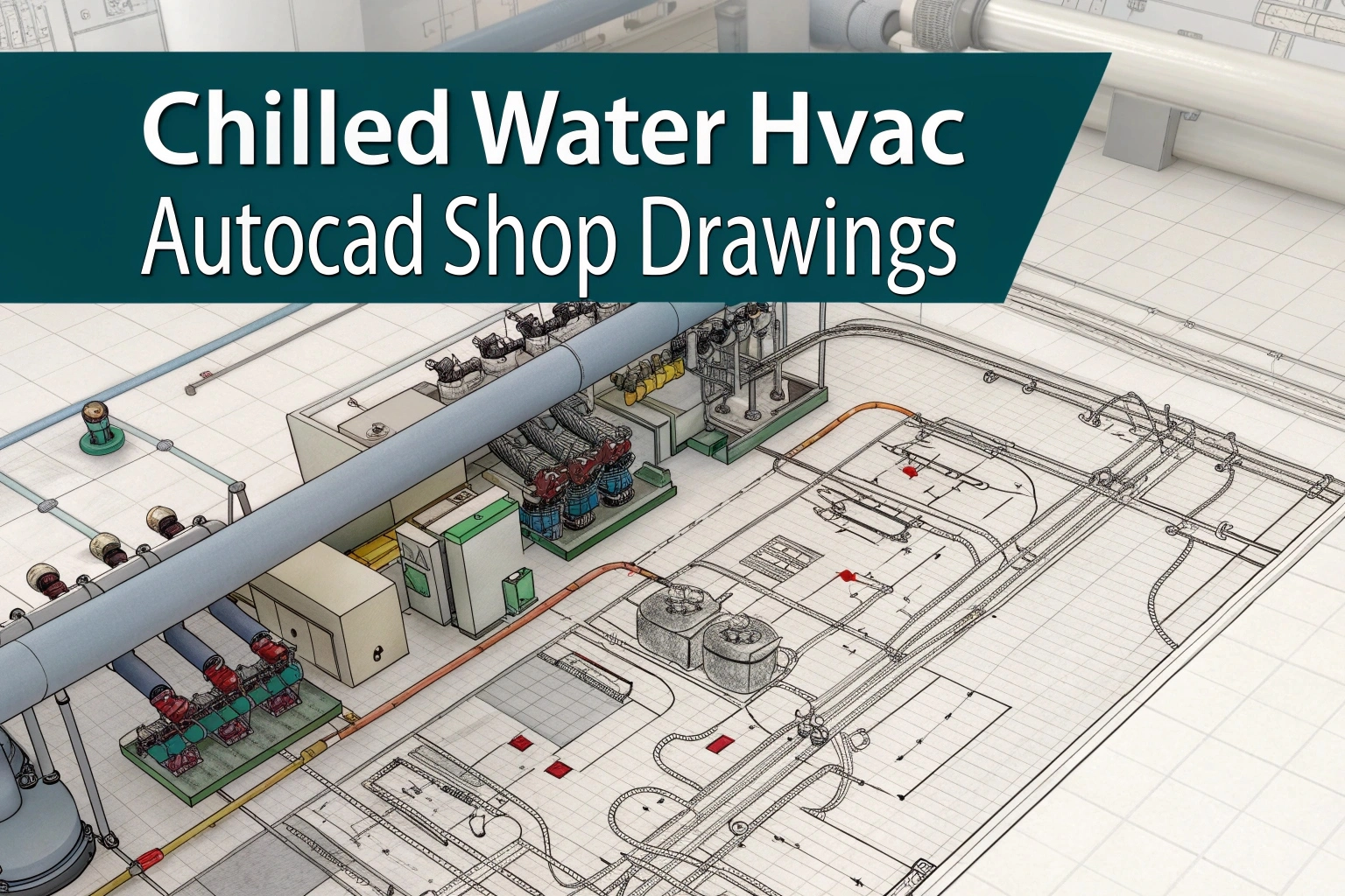
Creating precise shop drawings for a chilled water HVAC system can take hours of drafting. Our free AutoCAD DWG package streamlines that work. It delivers detailed floor‑by‑floor duct layouts alongside chilled water piping schematics. You’ll find air‑handling units, diffusers, and piping runs clearly annotated. Each drawing follows standard MEP layer conventions so you can drop them into your master model without extra editing.
Why These Drawings Save You Time
Rather than start from an empty canvas, you can reuse our pre‑drawn DWGs to speed up coordination. Structural, electrical, and plumbing teams will appreciate the clear clash‑detection layers. Meanwhile, contractors get fabrication‑ready details that minimize site error. This consistency helps you avoid costly rework and keeps your project on schedule. Plus, by adjusting only a few parameters—such as floor height or pipe size—you can tailor each sheet for any building in minutes.
Subscribe to Read Full Engineering Publication
This verified technical document contains complete mathematical derivations, IS/NBC 2016 code references, equipment sizing schedules, and AutoCAD DWG blueprints.
Have Specific Equipment or Plant Capacities to Calculate?
Our AI Specialist can troubleshoot technical issues, calculate duct velocity, determine chiller load, or size cables specifically for "Chilled Water HVAC AutoCAD Shop Drawings – Free".

popeye21834
Licensed Engineering ContributorChartered Senior MEP Engineer & Review Board Specialist with extensive design, testing, and commissioning field experience across commercial and industrial infrastructure.

Leave a Reply