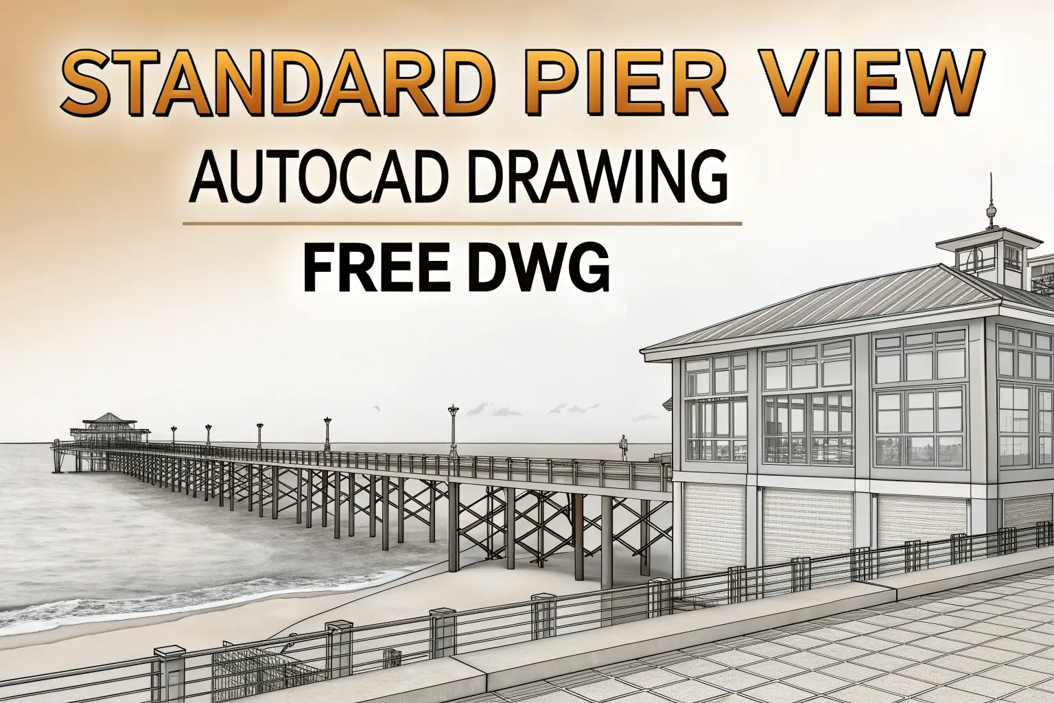
Standard Pier View AutoCAD: A precise pier view detail is essential for accurate bridge and foundation modelling. Our free AutoCAD DWG file delivers a fully dimensioned elevation and section of a standard pier, complete with footing geometry, pier shaft profiles, and reinforcement layout. By using this ready‑to‑use drawing, you’ll avoid hours of manual drafting and ensure every team member references the same clear, code‑compliant design.
Why This Pier View DWG Matters
First, the drawing shows exact footing widths and depths, making it simple to verify that foundations meet soil‑bearing requirements. It also illustrates reinforcement bar sizes and spacing, so your shop orders come through without mix‑ups. Additionally, clear labels and standard CAD layers let structural, geotechnical, and MEP teams integrate the pier detail into their own models without extra coordination steps. As a result, you reduce the risk of errors on site and speed up your approval process.
How to Incorporate the Drawing
After downloading the DWG, simply insert the block into your existing bridge or pier plan. You can adjust the scale to match your project’s dimensions or modify the reinforcement details to suit local codes. Because all elements—such as concrete grades, rebar marks, and centre lines—snap to standard layers, you maintain consistency across disciplines. Finally, share the file with fabricators and site crews so everyone works from the same up‑to‑date reference.
Download the Pier View AutoCAD DWG
Click the Google Drive link on the original page to grab your free DWG file. No sign‑in or subscription is required—download, open in AutoCAD, and start detailing your pier design right away.


