
Time Current Characteristics: Relays is used to protect power system from damage. they tripping when current is too high and its not safe. Time current curve is method to show when relays trip and how much current is flowing. its like graph with log log scale , horizontal axis show multiples of pickup and vertical axis show time in sec. so one chart can be use for many pickup settings and its very useful.
Why Use Log‑Log Paper?
Log scales is used to compress a lot of values in small space. they lets you to plot timing from 0.1 s to 1000 s in one paper. this is very useful because you can include many currents from 1 time to 100 time pickup without making it look messy.
Multiples of Pickup Simplify Curves
Relay A is having 2 A pickup and Relay B is having 5 A pickup they both are following same curve if we use multiples like if Relay A is having 3 times pickup then it sees 6 A and similarly Relay B sees 15 A so we can say that one curve is working for both devices.
How Induction Relays Trip
Induction relays is used to by relays to control spinning disk. they obtains torque using ampere-turn on disk, one of the most common technique is spinning disk, contacts closing and altering tap. they Use their coil turns to make contacts close on the disk like pickup tap, this is completely based on angle and still its very important.
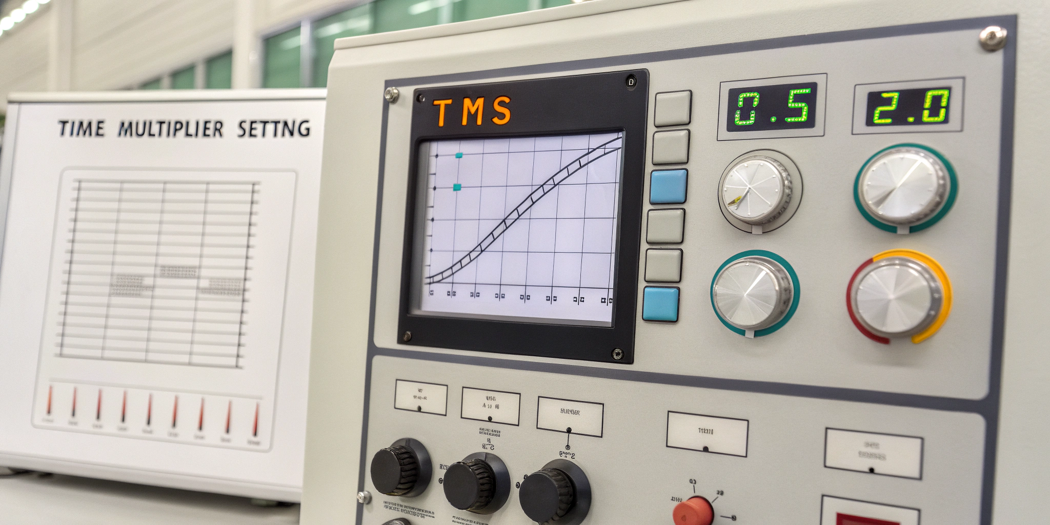
Introducing the Time Multiplier Setting
Time Current Characteristics: Manufacturers add a time multiplier setting (TMS) to adjust speed. A TMS of 1.0 shows the standard curve. Meanwhile, a TMS of 0.5 halves the trip time. Conversely, a TMS of 2.0 doubles it. By selecting an appropriate TMS, you coordinate fast and slow relays easily.
How to Read the Curve
- First, find your current multiple (fault current ÷ pickup current).
- Then, choose the proper TMS curve.
- Next, move up from the multiple until you hit the curve line.
- Finally, move left to read the trip time in seconds.
For example, a 4× multiple on TMS = 1.0 might read 0.8 s trip time.
Balancing Speed and Selectivity
Setting all relay to fastest TMS is possible but that’s not good ideal because multiple devices can trip at same time. better to use different TMS values so that every thing don’t trip together.
- End‑of‑line relay: TMS = 0.5 (fastest)
- Mid‑feeder relay: TMS = 1.0 (standard)
- Substation relay: TMS = 1.5 (slowest)
This approach ensures the closest relay trips first. Only if it fails does upstream backup kick in.
Handling Motor Inrush
Time Current Characteristics: Big motors take 6 to 10 times more current when they start. this thing can make overcurrent relay confused. so we set pickup at 1.5 times the locked rotor current or more. then we check curve trip time at 10 times pickup. if inrush current last for 0.3 sec and trip time is 0.5 sec then motor start without any problem.
Common Inverse‑Time Families
Relays typically offer three curve shapes:
- Standard Inverse: gentle slope for general feeders.
- Very Inverse: faster clearing at high currents.
- Extremely Inverse: sharp slope for tight discrimination.
Each family still use log log plotting but they emphasize different current ranges they obtain log log plotting using multiple methods one of the most common method is plotting , scaling and measuring they use their plotting to make analysis on the sites like graph , chart etc.
Steps to Coordinate Relays
- Run a short‑circuit study to find fault currents at each relay.
- Choose pickup settings above load current and below minimum fault current.
- Select TMS values that leave a 0.2 s coordination margin.
- Plot all curves on one log‑log sheet.
- Field‑test by injecting currents and measuring actual trip times.
- Update settings whenever network or load conditions change.
Why Paper Curves Still Matter
Time Current Characteristics: Digital relays have digital display and all that. but still paper plots is very useful in field. they obtains information using multiple techniques one of the most common technique is to find miscoordination and aging problem very fastely. they Use their chart info to make adjustment on the sites like substations, power plants etc. this is completely helpful all over the world and still its very popular to technicians.
Time Current Characteristics: FAQs
1. Why use log‑log paper?
Log scales compress wide value ranges and keep the chart tidy.
2. What is “multiple of pickup”?
It equals fault current divided by the relay’s set pickup current.
3. How does TMS affect trip time?
TMS scales trip time: less than 1 speeds up trips; greater than 1 slows them down.
4. How do I prevent motor start up trips?
Raise pickup above inrush current and confirm trip time exceeds inrush duration.
5. Which inverse‑time curve should I choose?
Use Standard for general feeders, Very or Extremely Inverse for fast, high‑current fault clearing.
6. How often should I re‑check settings?
Review after network changes, load growth, or unexpected relay operations.
READ ALSO: Voltage to Current Converter
